Common Mode Measurement
To do common mode measurements (explanation here) with the CAN-Bus Tester 2, you need a DSO, triggered by the CBT2’s trigger output. Start a continuous measurement of the node you want to trigger to (the first message in the oscillogram).
You will see pictures like this:
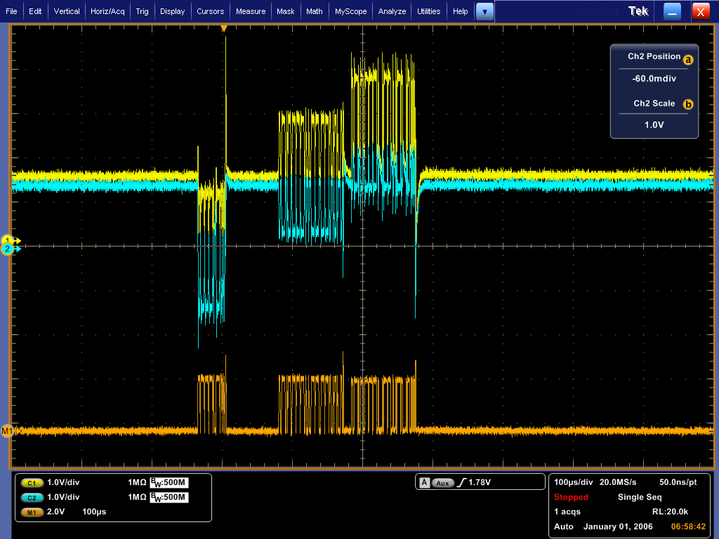
The CAN-Bus Tester 2 cannot measure absolute values, that’s why it only see’s the differential signal, which is displayed orange in the oscillogram. The oscilloscope shows the potential differences. Messages that only occur in bigger intervals should be measured individually.
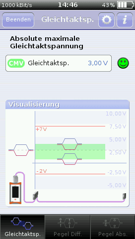 Easier is this measurement with the CANtouch. It can measure absolute values against a reference potential, values the measured data and shows the case in the upper oscillogram on the same bus as displayed left.
It is clear that we have messages with potentials higher and lower to the measurement point. The common mode voltage is 3,00 V at all.
To do the same with the CBT2, one would need the tester, a laptop, the DSO and power for every item. All this must be connected and the DSO must be properly adjusted. With CANtouch the single thing to do is to connect the bus – switch on and you are ready to start.
We found a better name for this problem recently. Now we call it “ground shift”, that describes this problem much better.
 |
 |
| 2018/07/06 | 2017/01/03 |